SunFounder sent us a sample of the Pironman 5 Pro Max tower PC case for Raspberry Pi 5 for review along with a PiPower 5 UPS board. The “Pro Max” builds upon the Pironman 5 Max we reviewed last year, adding a 4.3-inch capacitive touchscreen display, a 5MP camera module, two speakers, a USB microphone, and a 3.5mm audio jack. The PiPower 5 is a UPS HAT designed for Raspberry Pi Zero/Model B single-board computers, and not directly compatible with the Pironman cases, but we’ll still try to use it.
I’ll start this review with an unboxing of the Pironman 5 Pro Max and PiPower 5 packages, followed by an assembly guide for the Pironman 5 Pro Max, a test of the new features (display, camera, audio interaction), and finally, I’ll have a quick test of the UPS HAT with the Raspberry Pi 5 enclosure.
Unboxing of Pironman 5 Pro Max and PiPower 5
I received two retail packages for the devices. The PiPower 5 package had a rough trip and was a bit damaged, but more importantly, its content survived.
Each package provides basic information. The PiPower 5 ships with a 2,000 mAh battery, supports up to 45W DC input (5/15V via USB-C), outputs up to 5V/5A, and implements I2C battery monitoring and safe shutdown. The Pironman 5 Pro Max includes a 4.3-inch IPS display, two M.2 sockets, a 5MP camera (written 500 MP due to a mistranslation), a 0.96-inch OLED, three RGB fans, two speakers, and a USB microphone.
Assembly of the case involves many more parts than the original Pironman 5 case, so reserve about two hours to assemble the Pro Max enclosure with a Raspberry Pi 5. I was unable to find the usual printed assembly guide included with previous versions, which was a disappointment.
Let’s open the PiPower 5 package. It ships with the PiPower 5 HAT+, a 7.4V/2,000 mAh Lithium-ion battery, an acrylic plate, a screwdriver, a wrench, various zip bags with screws, standoffs, a heatsink, and an assembly guide.
The bottom side of the PiPower 5 HAT+ lists basic features of the board:
USB Type-C – 5V/3, 9V/3A, 12V/3A, 15V/5A power input
Screw terminal – 5V-15V DC input
Output – 5V/5A
Charge power – Up to 20W
Battery – 7.4 2S Li-Ion
Pironman 5 Pro Max assembly
I usually start working on my computer at 9 am, and will typically perform tasks like teardown and assembly earlier in the morning without using my phone or laptop. But the assembly guide was not provided in the package, so I went to the documentation page and printed the “assembly instructions” (PDF) out myself on A4 paper. The guide is not designed for this paper size, so the text was rather small and hard to read. I eventually managed, but not before making a few errors due to misreading a couple of times.
The build instructions are very similar to the ones for the Pironman 5 Max enclosure, so I haven’t taken as many photos this time around. Assembly starts by separating the two metal parts of the case, installing the Pironman 5 HDMI USB adapter and your own Raspberry Pi 5 with the microSD card extender, and inserting various cables (MIPI, PCIe, fan) and the two speakers. I also added the three thermal pads provided in the kit.
Two important steps here are to insert the provided RTC battery and cable (I completely forgot about these two), insert the 4-pin power header, and configure the speaker jumper (left default: ON). I had to reopen the case to insert the RTC battery and cable, and let’s say it’s much better to do it while assembling the case than after.
After that, I installed the ICE cooler, inserted the dual NVMe PiP and Pironman 5 Pro Max HAT+ boards, connected the wires as instructed, and also installed an NVMe SSD and a Hailo-8 AI accelerator (my own parts, not part of the kit).
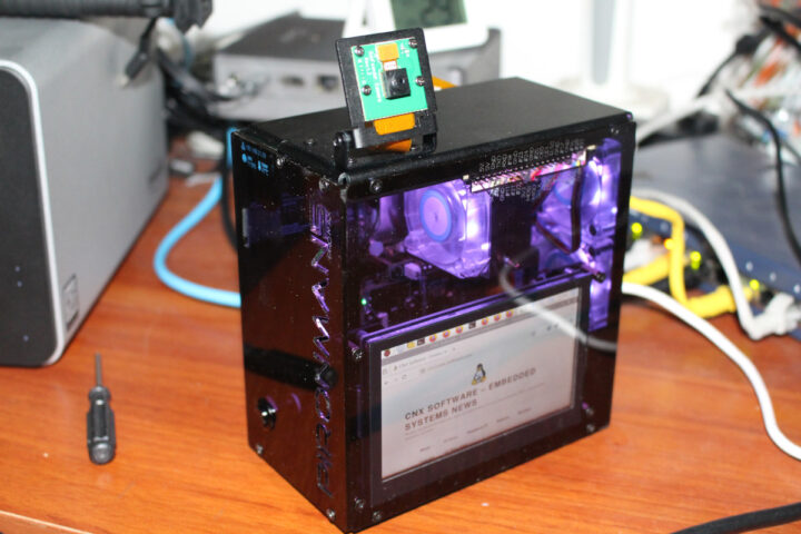
We can now work on the second metal part by installing two RGB LED fans and two speakers on it. I also added the OLED (bottom left) and inserted the MIPI CSI cable into the camera opening.
We can now secure both metal parts of the enclosures and